


SWR ANTENNA
TUNING
Read SWR on channels 1, 20, and 40. We'll tell you whether to raise or lower your antenna, how big an adjustment to make, and how much transmit power you're losing to mismatch at current tune.
What tuning actually does
Your radio is built to deliver power into a 50 ohm load. Your coax cable is 50 ohm. Your antenna, when cut to the right electrical length for the frequency you're on, also presents 50 ohms at the feedpoint. When all three match, power flows out cleanly and SWR reads 1.0.
When the antenna is electrically too long or too short for the frequency, the feedpoint impedance drifts off 50 ohms. The coax can't transfer all the power cleanly into that mismatched load, so some of it bounces back — that's your reflected power, and that's what the SWR meter reads. Tuning an antenna is literally the act of returning the feedpoint impedance to 50 ohms at your operating frequency.
The coax matters too
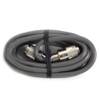
Feedline impedance is just as important as antenna impedance. CB and 10 meter radio systems require 50 ohm coax — usually RG8X, RG58, or RG8/LMR‑400 for longer runs. If the coax is the wrong impedance, there's nothing you can do to the antenna to fix it.
Cheap or counterfeit coax is a real problem in this hobby. Budget cable sold as "RG8X" online sometimes tests at 60–75 ohms because the center conductor, dielectric, or shield isn't built to spec. A cable that measures 70 ohms will give you an SWR of at least 1.4 no matter how perfectly your antenna is tuned — the mismatch is baked into the cable. This is a common reason people can't get a short antenna below a 2.0 SWR even after hours of tuning.
If your SWR is high across all three channels, or if tuning isn't bringing it down, the problem is almost never the antenna by itself. Here are the five failure modes we see most often in our repair shop, in roughly the order you should check them.
Insufficient Ground Plane
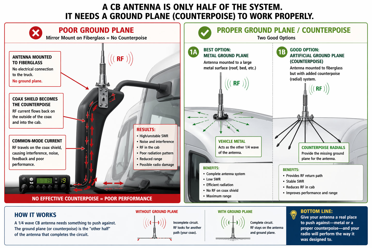
A CB antenna needs metal underneath it to radiate properly. That metal acts as the other half of the antenna — the counterpoise. Without enough metal under the mount, the antenna can't develop a proper 50 ohm feedpoint impedance, so SWR stays high no matter how you tune it.
Mounts on plastic surfaces (fiberglass RVs, plastic truck bed rails, composite panels) have zero ground plane and will never tune to a low SWR with a standard antenna — you need a no-ground-plane (NGP) antenna system instead.
Mounts on small metal surfaces (mirror brackets, small tool boxes, short hoods) often have insufficient ground plane. The antenna works, but SWR bottoms out around 2.0 regardless of tuning. The fix is a larger mount location, a longer antenna that's less ground-plane-dependent, or a ground plane kit that adds radial wires under the mount.
Antenna Stud Installed Upside-Down
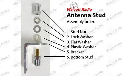
Antenna studs use a stack of washers to electrically isolate the stud's hot conductor from the vehicle mount while holding everything firmly in place. From top to bottom, the correct order is: stud nut (where the antenna screws on), locking metal washer, flat metal washer, plastic isolation washer, then the mount, with the bottom of the stud passing through and securing underneath. The plastic isolation washer is the critical piece — it sits directly on top of the mount, between the metal washers above and the mount below, which keeps the hot side of the stud electrically separated from the vehicle chassis.
If the plastic isolation washer ends up on the bottom side of the mount instead of the top — or gets left off entirely — the hot terminal of the stud makes direct metal-to-metal contact with the mount and the vehicle chassis. Now your radio is transmitting into a dead short instead of an antenna. The meter will read pegged or infinite SWR, and you can take out the final transistor on the very first key-up.
How to verify: with the coax disconnected from the radio, touch a multimeter between the center pin of the PL-259 and the outer shell. You should read infinite resistance (open circuit). If you read continuity or a low ohm value, the stud is shorted — pull it off the mount, re-stack the washers in the correct order, and reinstall.
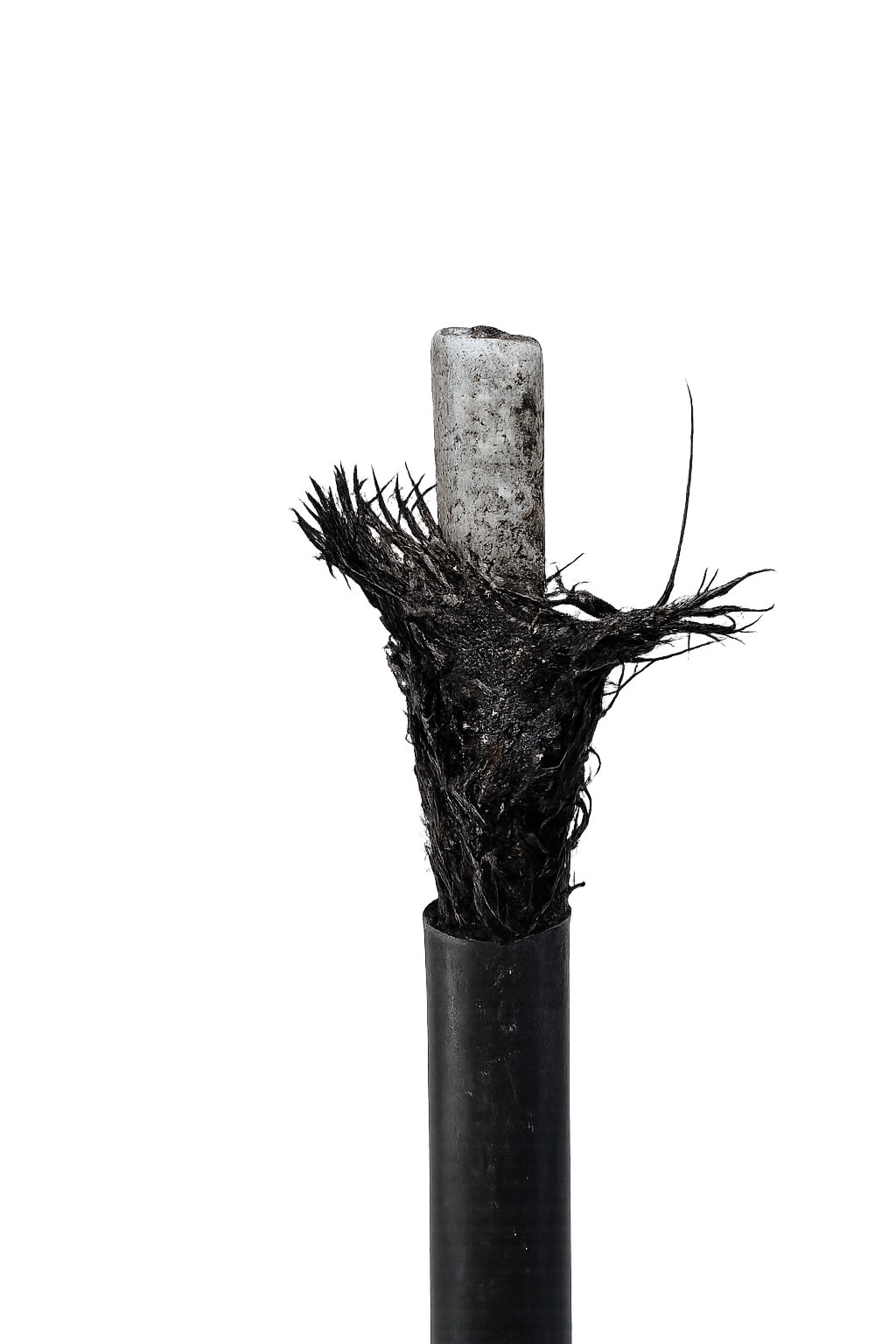
Broken or Damaged Antenna
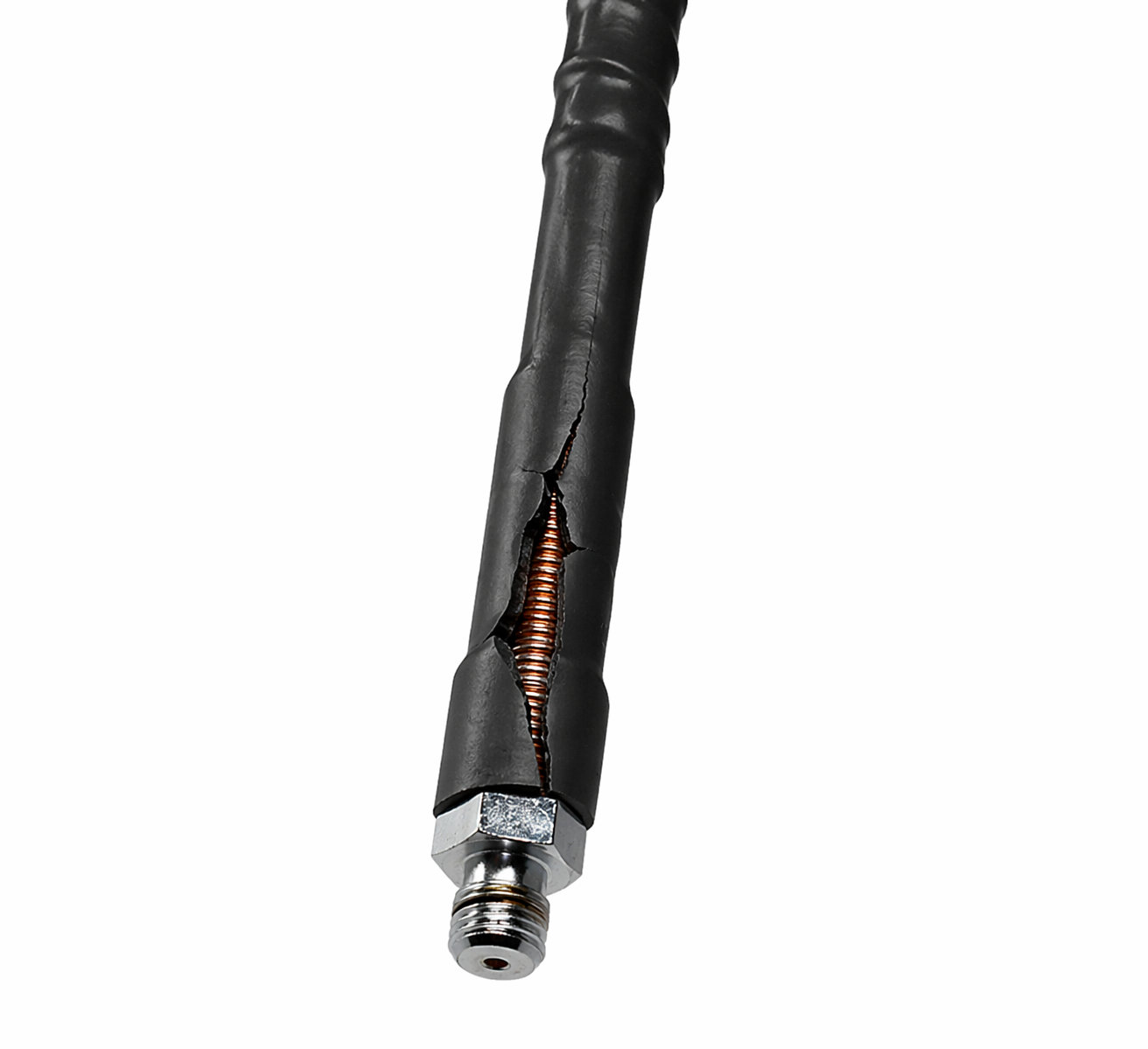
Fiberglass antennas are internally wound — a coil of wire wrapped around a fiberglass core, sealed under the outer jacket. When the antenna takes a hit (low bridge, tree branch, rollover in a parking lot), the wind winding or the electrical connection at the base can break even if the outside still looks mostly intact.
What to look for: flex the base of the antenna with your hand. If it bends freely or makes a crunching sound, the fiberglass core is cracked. Inspect the bottom 6 inches for hairline cracks, moisture intrusion, discoloration, or any separation between the base stud and the fiberglass body. A damaged base will often look fine visually until you look closely at the seam where the metal stud meets the fiberglass.
Steel whip antennas fail differently — check the coil at the base (if equipped) and the continuity between the tip of the whip and the stud with a multimeter. No continuity means the whip has an internal break.
Coax Cable or Connector Problems

Coax fails in three common ways: a broken solder joint at a PL-259 connector, a kink or crush that damages the center conductor or shield along the run, or the cable itself being off-spec impedance from a cheap manufacturer.
Connector failures usually happen where the coax gets flexed repeatedly — where it enters the cab, where it attaches to the antenna mount, or where it plugs into the radio. Inspect both PL-259s for a loose or twisting shell, green corrosion around the center pin, or the outer shield pulling back from the connector body. A properly soldered PL-259 will feel solid with no wiggle.
Cable damage can be hard to see. Feel the full length of the coax for sudden bumps (crushed sections), sharp bends it won't recover from (kinks), or soft spots where the jacket has been cut. Any of these can short the center conductor to the shield or break it entirely.
Off-spec cheap coax is the hardest to diagnose without test equipment. If you've verified your antenna, mount, stud, and ground plane are all good and SWR still won't come down below about 1.5–2.0 with a short antenna, swap in known-good 50 ohm coax and re-measure. A real RG8X from a reputable manufacturer will often pull the reading down noticeably compared to a no-name cable.
Nearby Metal or Parallel Antennas
A CB antenna is sensitive to what's around it. Any large metal object within a few feet — parallel tool box, mirror arm, a second antenna on a matching mount — can couple to your antenna and change its effective impedance. You're tuning one antenna, but electrically you have two antennas interacting.
Dual antenna setups must be tuned as a pair. Adjust one, measure, adjust the other the same amount, re-measure. Never try to tune one while the other is installed differently — you'll chase your tail.
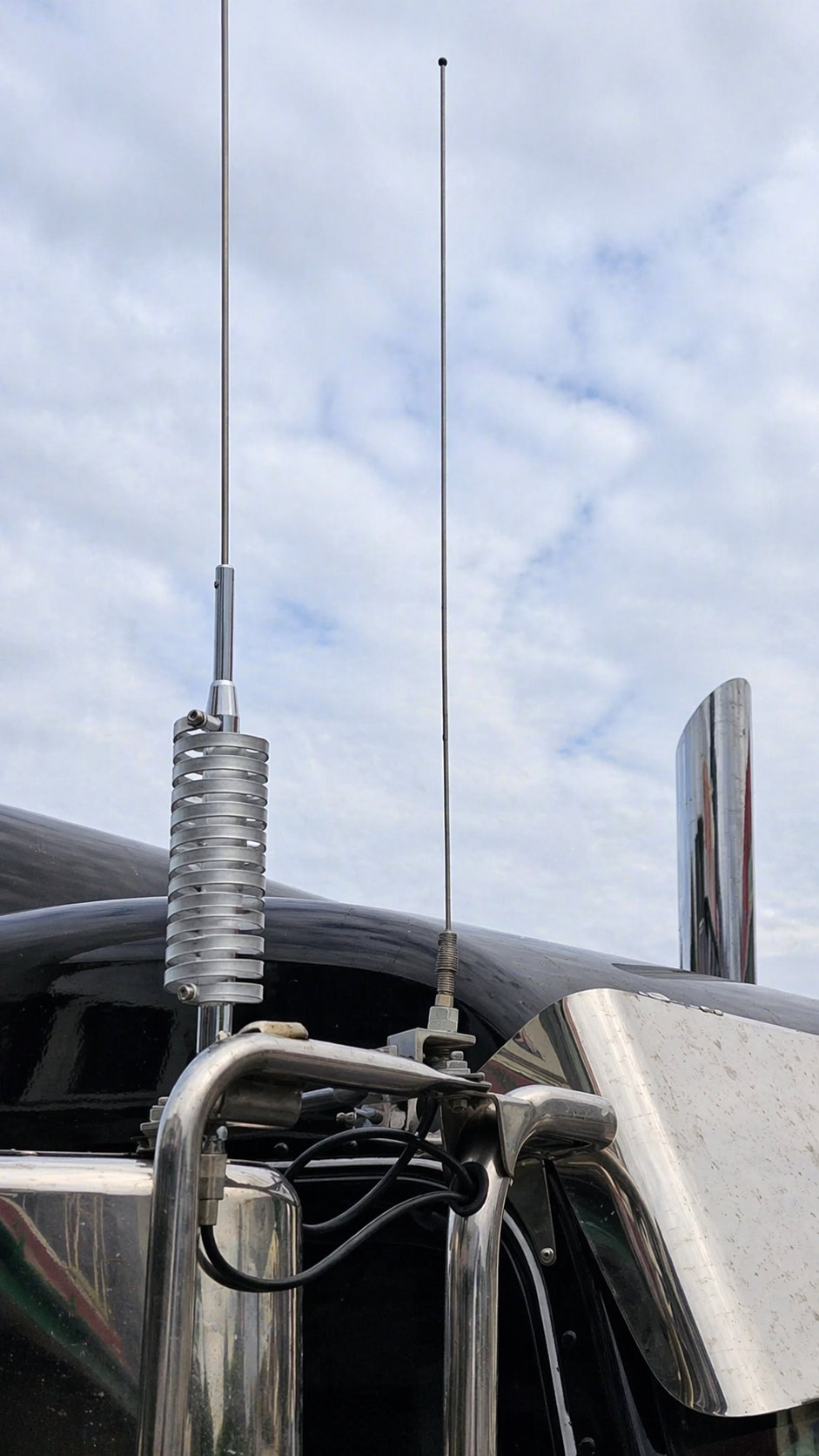
Semi-truck smokestacks are a specific and common source of this problem. Many big rigs — Peterbilts in particular, but also Kenworths and Freightliners with tall polished stacks — carry large-diameter vertical metal pipes running right next to the cab where antennas are typically mounted. That stack is essentially a large parasitic antenna element sitting parallel to your CB antenna. RF couples between the two and shifts your antenna's effective impedance, which means you may not be able to get a clean SWR tune no matter what you do to the antenna itself. If you're tuning a dual-antenna setup with matched stacks on both sides of the cab you can often work around it; if you have a single antenna mounted on the same side as a single stack, consider moving the antenna to the opposite mirror or as high up on the cab as possible to get some separation.
Single antennas next to tall flat surfaces (the back of a cab, a trailer wall, a shop door) will show SWR changes when the environment changes — for example, low SWR in the shop, high SWR on the road. Move the antenna to a more open mount location if possible, or accept the readings taken in the actual operating environment.
How to use this tool. Key up on a dead channel with full power and take an SWR reading on channels 1, 20, and 40. Enter those numbers above. The tool compares the edge readings (1 and 40) to tell you which way the antenna is off — lower Ch1 SWR means the antenna is tuned too low (too long) and needs to come down, lower Ch40 SWR means it's tuned too high (too short) and needs to go up. Adjust, re‑measure, and repeat until Ch1 and Ch40 match. Your Ch20 reading is then your true antenna performance.
What's a good SWR? Anything under 1.5 is excellent, 1.5–2.0 is good, 2.0–2.5 is acceptable, 2.5–3.0 is marginal, and 3.0 or higher is a warning — transmitting above 3.0 SWR can damage the output transistors in your radio. Short fiberglass antennas typically land in the 1.5–2.0 range at their best; taller steel whips can pull below 1.2. If you can't get below 2.5 anywhere in the band, you likely have a ground plane, coax, or mount issue rather than a tuning problem.
Power loss math. Reflection coefficient Γ = (SWR−1) / (SWR+1). Fraction of forward power reflected is Γ², so delivered fraction is 1 − Γ². At SWR 2.0 that's 11% lost; at SWR 3.0 it's 25% lost. Reflected power doesn't vanish — it bounces back into the transmitter as heat, which is why high SWR shortens finals life.